
In the second part of our Digital Solutions for Naval Architecture blog series, we look at Digital Dry Dock’s recent work on the Isles of Scilly inter-island passenger ferries. Through our services, we were able to ensure the ferries complied with naval architectural standards, maintaining optimum safety for its crew and passengers.
Isles of Scilly Passenger Ferries
The Isles of Scilly is a remote archipelago, 28 miles from the Cornish mainland. With over 140 islands, the smallest no larger than a rock and the largest no bigger than three by two miles, the inter-island passenger ferries are an essential part of life in this remote corner of the United Kingdom. The ferries run services between the five inhabited islands – St Mary’s, Tresco, St Martin’s, Bryher and St Agnes. They also run routes to Samson, the largest of the uninhabited islands.
Earlier this year, five of the inter-island passenger ferries had their draught mark positions in question by the surveying authorities – the Maritime and Coastguard Agency (MCA) and a naval architect. Draught marks are used by the master to ensure that the vessel is not overloaded, as according to its stability book datums, before leaving port.
Digital Solutions for Complying with Naval Architectural Standards
Being in a remote location, traditional methods of checking draught mark positions require boat owners in the Scillies to spend multiple days, or even weeks, travelling to mainland boatyards and having work carried out. To save the time, hassle and costs of doing so in addition to their annual haul out and maintenance period on the mainland, the ferry owners asked Digital Dry Dock if we could complete the work alongside the routine maintenance work.
By conducting a 3D laser scan survey of the vessels, we were able to create an accurate ‘as-built’ digital twin for each vessel, working around other contractors who were conducting GRP modifications, engineering works, antifouling and painting work. After scanning, we applied the stability book datums to the models, to determine where the draught marks should be compared to where they had been marked so far on the hull.
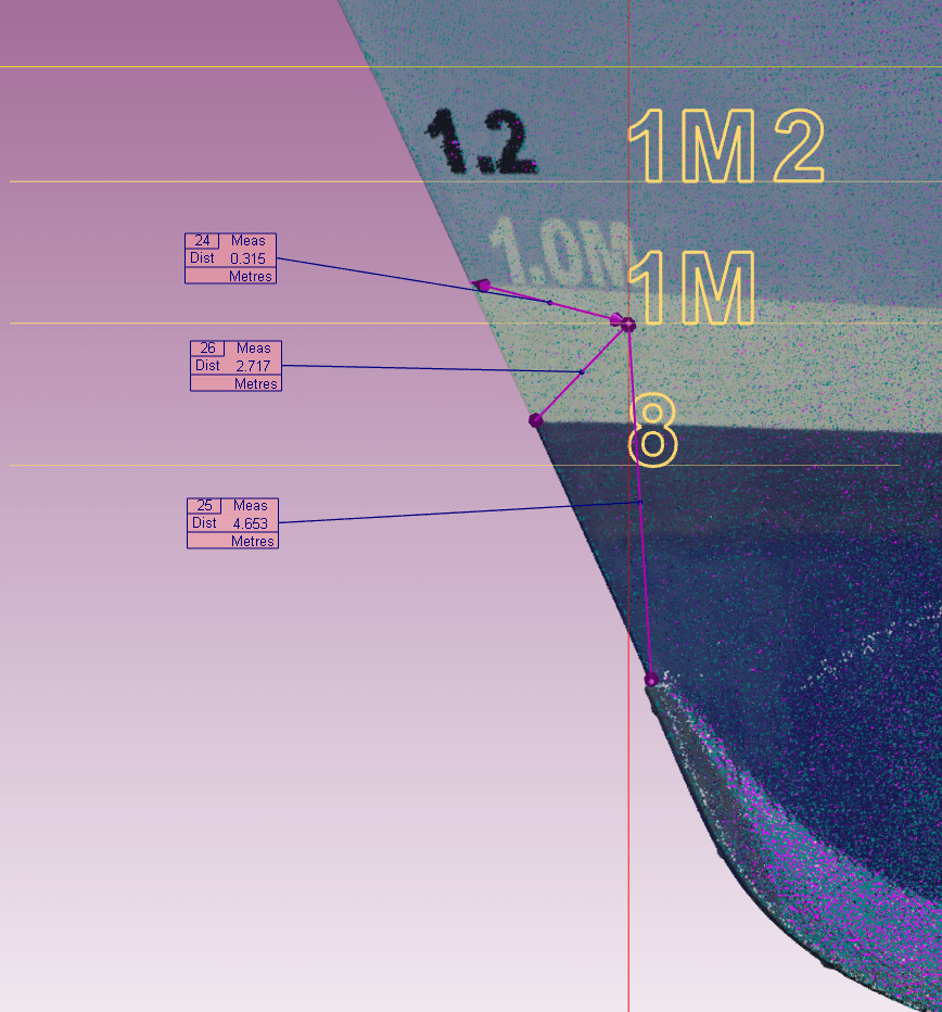
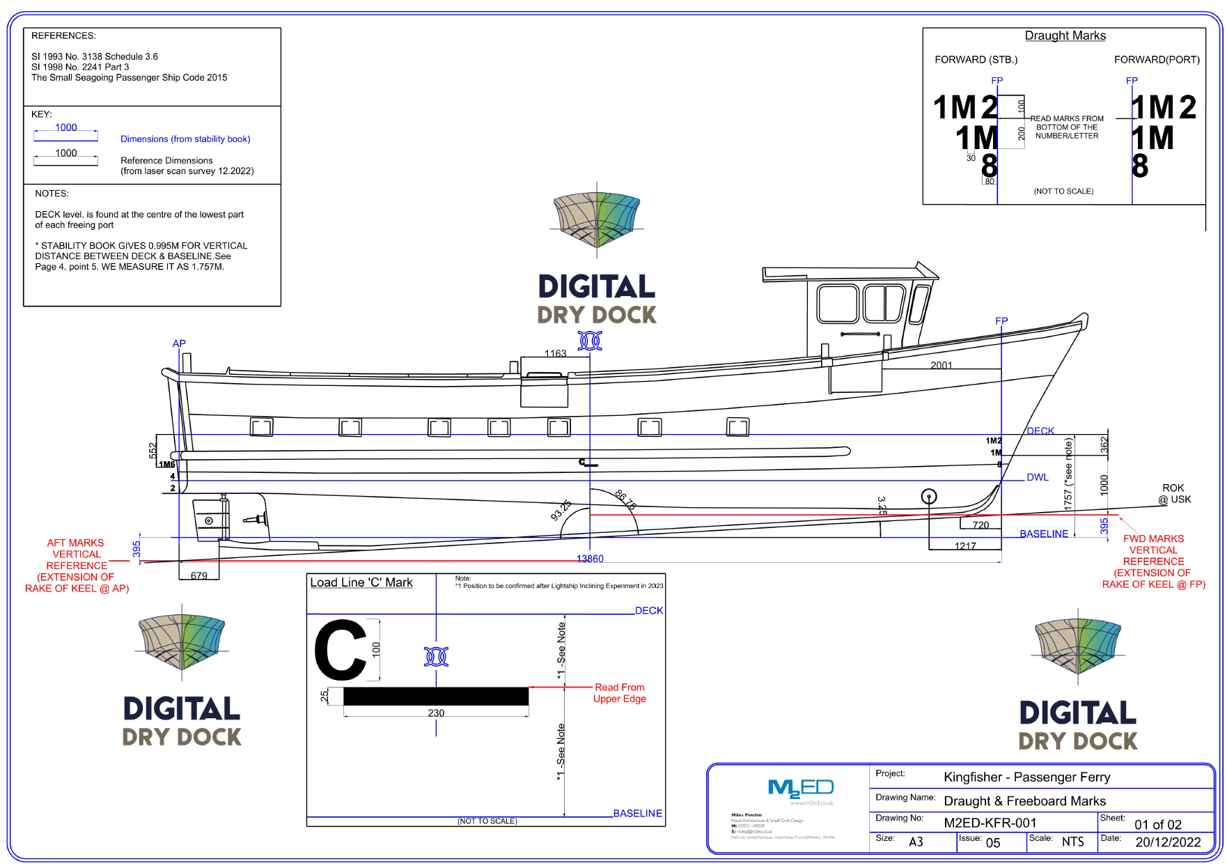
The next step was to produce a 2D CAD drawing which could be used to show the correct position, size and spacing of the marks. This drawing included measurements taken from the digital twin, which allowed us to position them with far greater accuracy than traditional methods calculated by hand, as well as saving ferry owners time and money by limiting their time on the dry dock.
The Result
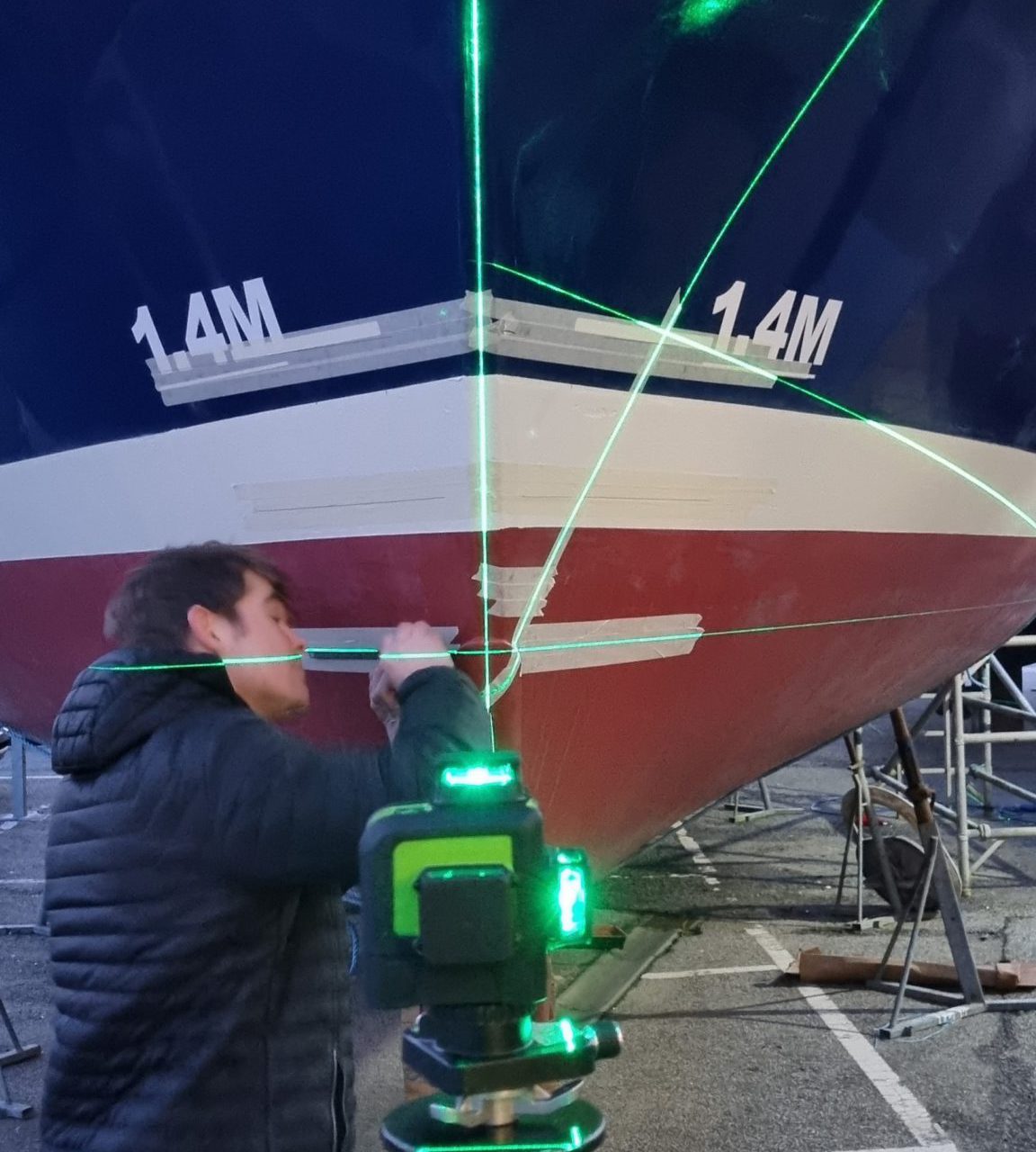
With our method approved by the MCA we were able to CNC laser cut new marks and install them on the beach in St Mary’s, saving the vessel owners an additional trip to the mainland. Our methods also made it possible to avoid the arduous, time-intensive and costly process of manually levelling the vessels to ‘real world level’ before positioning the marks. By using 3-axis laser levels with a survey grade elevating tripod to lay them out, we were able to position the marks within an hour. These positions were then verified by the MCA before we installed them on the GRP hulls with a permanent mastic adhesive.
As a result, the naval architect and MCA are now satisfied that all five ferries’ draught marks comply with naval architectural standards.